
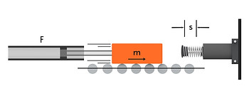
Sizing Industrial Shock Absorbers for Mass With Propelling Force
Industrial shock absorbers play a critical role in safely decelerating moving masses influenced by external forces. This guide explains how to size shock absorbers for cases where a mass is propelled by an external force.
CALCULATION CONCEPTS
-
Kinetic Energy (W1): The energy possessed by a moving mass due to its velocity.
-
Formula: W1 = 1/2 * m * v^2
-
Significance: This is the primary energy that the shock absorber must dissipate to bring the moving mass to a complete stop.
-
-
Propelling Energy (W2): Propelling energy is the energy used to drive or push an object forward.
-
Formula: W2 = F⋅s
-
Energy added by the external force FFF acting over stroke s.
-
-
Total Energy Per Stroke (W3): In the presents of external propelling forces, the total energy to be absorbed by the shock absorber is equal to the kinetic energy of the moving mass.
-
Formula: W3 = W1 + W2
-
-
Load Factor: The ratio of the total energy per stroke (W3) to the shock absorber's maximum allowable energy capacity.
-
Formula: Load Factor = (W3 / W3per) * 100
-
Recommendation: For optimal performance and durability, the load factor should ideally be below 80%.
-
-
Impact Speed (vD): The velocity of the mass at the moment of impact with the shock absorber. In this case, it is equal to the initial velocity of the moving mass (v).
-
Effective Mass (me): The equivalent mass experienced by the shock absorber during deceleration. It ensures smooth deceleration over the entire stroke length.
-
Formula: me = W3 / (1/2 * v^2)
-
Note: The effective mass must fall within the shock absorber's specified permissible range.
-
-
Deceleration Time (t): The time required to bring the moving mass to a complete stop.
-
Approximate Formula: t ≈ 2.6 * s / vD
-
Note: Shorter deceleration times generally result in higher forces on the shock absorber.
-
-
Supporting Force (Q): The force exerted by the shock absorber to decelerate the mass.
-
Formula: Q = 1.5 * W3 / s
-
Note: The structure to which the shock absorber is mounted must be adequately designed to withstand this force.
-
-
Cycles Per Hour (x): The number of impacts the shock absorber experiences within one hour.
-
Formula: x = 3600 / (t_reset + t)
-
Note: The actual number of cycles per hour must not exceed the shock absorber's maximum permissible cycles per hour (xper).
-
SIZING PROCEDURE
-
Gather Input Data:
-
Mass of the object (m) in kilograms.
-
Velocity at impact (v) in meters per second.
-
Desired stroke length (s) in meters.
-
Number of cycles per hour (x) in impacts/hour.
-
-
Calculate Total Energy Per Stroke (W3): Use the formula W3 = 1/2 * m * v^2.
-
Determine Effective Mass (me): Calculate me using the formula me = W3 / (1/2 * v^2) and ensure it falls within the acceptable range for the shock absorber.
-
Estimate Deceleration Time (t): Calculate t using the approximate formula t ≈ 2.6 * s / vD.
-
Verify Supporting Force (Q): Calculate Q using the formula Q = 1.5 * W3 / s and ensure the mounting structure can withstand this force.
-
Check Load Factor and Cycles Per Hour:
-
Calculate the Load Factor and ensure it is below 80% for optimal performance.
-
Verify that the actual cycles per hour (x) do not exceed the maximum permissible cycles per hour (xper) for the shock absorber.
-
Example Calculation
-
Given:
-
Mass (m) = 36 kg
-
Force (F) = 400N
-
Velocity (v) = 1.5 m/s
-
Stroke Length (s) = 0.025 m
-
Cycles/hours (n) = 1000
-
-
Step 1: Calculate W1:
-
W3 = 1/2 * 36 kg * (1.5 m/s)^2 = 41 Nm
-
-
Step 2: Calculate W2:
-
W2= 400 x 0.025 = 10 Nm
-
-
Step 3: Calculate W3:
-
W1+W2=41+10=51Nm
-
-
Step 4: Calculate W4:
-
E4=W3 x n =51⋅1000=51,000Nm/hour
-
-
Step 5: Calculate me:
-
me = 2 x 51/1.5² = 48 kg
-
-
Step 6: Calculate: t = 1.52 x 6 x 0.025 = 0.043 seconds
-
Step 7: Calculate: Q=1.5 x 51/0.025 = 3,060N
Note: This is a simplified guide. For precise sizing, consider factors like operating temperature, environmental conditions, and specific shock absorber characteristics.