
Sizing Industrial Shock Absorbers for Mass Without Propelling Force
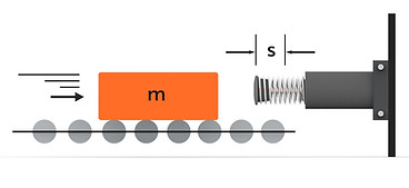
Industrial shock absorbers are crucial components in engineering systems designed to safely decelerate moving objects, preventing damage and ensuring smooth operation. This guide focuses on sizing shock absorbers for scenarios where a mass moves without any external propelling force, such as a falling object or a freely moving component.
CALCULATION CONCEPTS
-
Kinetic Energy (W1): The energy possessed by a moving mass due to its velocity.
-
Formula: W1 = 1/2 * m * v^2
-
Significance: This is the primary energy that the shock absorber must dissipate to bring the moving mass to a complete stop.
-
-
Total Energy Per Stroke (W3): In the absence of external propelling forces, the total energy to be absorbed by the shock absorber is equal to the kinetic energy of the moving mass.
-
Formula: W3 = W1 + W2 (where W2 = 0 for no propelling force)
-
-
Load Factor: The ratio of the total energy per stroke (W3) to the shock absorber's maximum allowable energy capacity.
-
Formula: Load Factor = (W3 / W3per) * 100
-
Recommendation: For optimal performance and durability, the load factor should ideally be below 80%.
-
-
Impact Speed (vD): The velocity of the mass at the moment of impact with the shock absorber. In this case, it is equal to the initial velocity of the moving mass (v).
-
Effective Mass (me): The equivalent mass experienced by the shock absorber during deceleration. It ensures smooth deceleration over the entire stroke length.
-
Formula: me = W3 / (1/2 * v^2)
-
Note: The effective mass must fall within the shock absorber's specified permissible range.
-
-
Deceleration Time (t): The time required to bring the moving mass to a complete stop.
-
Approximate Formula: t ≈ 2.6 * s / vD
-
Note: Shorter deceleration times generally result in higher forces on the shock absorber.
-
-
Supporting Force (Q): The force exerted by the shock absorber to decelerate the mass.
-
Formula: Q = 1.5 * W3 / s
-
Note: The structure to which the shock absorber is mounted must be adequately designed to withstand this force.
-
-
Cycles Per Hour (x): The number of impacts the shock absorber experiences within one hour.
-
Formula: x = 3600 / (t_reset + t)
-
Note: The actual number of cycles per hour must not exceed the shock absorber's maximum permissible cycles per hour (xper).
-
SIZING PROCEDURE
-
Gather Input Data:
-
Mass of the object (m) in kilograms
-
Velocity at impact (v) in meters per second
-
Desired stroke length (s) in meters
-
Number of cycles per hour (x) in impacts/hour
-
-
Calculate Total Energy Per Stroke (W3): Use the formula W3 = 1/2 * m * v^2
-
Determine Effective Mass (me): Calculate me using the formula me = W3 / (1/2 * v^2) and ensure it falls within the acceptable range for the shock absorber.
-
Estimate Deceleration Time (t): Calculate t using the approximate formula t ≈ 2.6 * s / vD.
-
Verify Supporting Force (Q): Calculate Q using the formula Q = 1.5 * W3 / s and ensure the mounting structure can withstand this force.
-
Check Load Factor and Cycles Per Hour:
-
Calculate the Load Factor and ensure it is below 80% for optimal performance.
-
Verify that the actual cycles per hour (x) do not exceed the maximum permissible cycles per hour (xper) for the shock absorber.
-
Example Calculation
-
Given:
-
Mass (m) = 100 kg
-
Velocity (v) = 3 m/s
-
Stroke Length (s) = 0.3 m
-
-
Step 1: Calculate W3:
-
W3 = 1/2 * 100 kg * (3 m/s)^2 = 450 Nm
-
-
Step 2: Determine me:
-
me = 450 Nm / (1/2 * (3 m/s)^2) = 100 kg
-
-
Step 3: Estimate t:
-
t ≈ 2.6 * 0.3 m / 3 m/s = 0.26 s
-
-
Step 4: Verify Q:
-
Q = 1.5 * 450 Nm / 0.3 m = 2250 N
-
Note: This is a simplified guide. For precise sizing, consider factors like operating temperature, environmental conditions, and specific shock absorber characteristics.